Figure 1. System schematic of automated system, blue boxes represent control boxes fitted with sensors and peristaltic pumps. Solenoid valves not pictured.
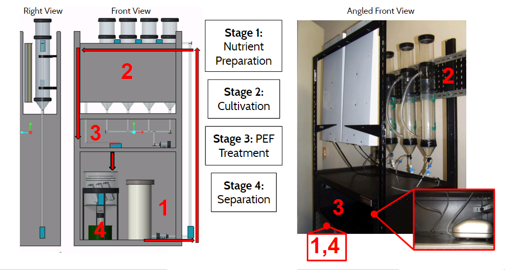
Figure 2. Expanded CAD and picture of system with all components labeled and direction of process shown.

Figure 3. Algae set up in CAPS Alternative Energy Lab. Algae growth is enabled using UV lights and an air pump to distribute CO2.
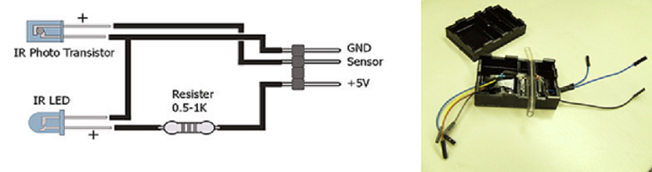
Figure 4. IR - phototransistor black box sensors, (left) schematic and (right) constructed sensor used to control automation based on cellular density.
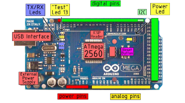
Figure 5. Arduino Mega 2560 Microcontroller used for system automation. Important parts of the board are labeled.
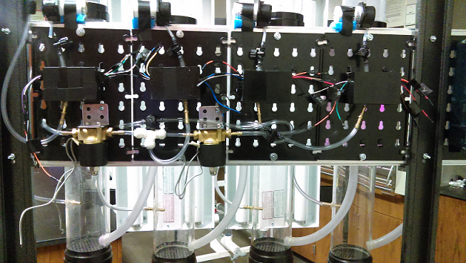
Figure 6. Wiring of system automation, solenoids (gold) and IR - phototransistor boxes (black) shown.
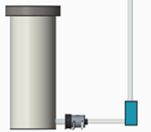
Figure 7. CAD of nutrient/medium holder, stored within cabinet portion of system (stage 1).
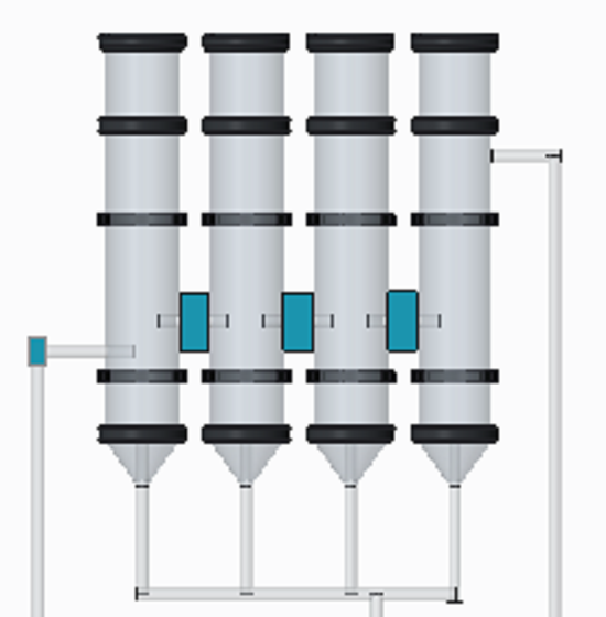
Figure 8. CAD of airlift cultivation stage (2) of the system.
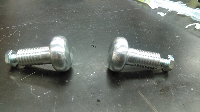
Figure 9. Modified Bruce Electrodes.

Figure 10. Exploded View of pulsed electric field (PEF) treatment set up including chambers and modified Bruce electrodes.
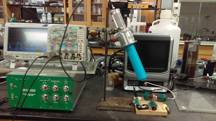
Figure 11. Demo set up of PEF treatment stage to illustrate arcing and break down point in air.

Figure 12. High voltage testing set up for quantification of PEF output.

Figure 13. CAD of modified lamella separator used to facilitate sedimentation of PEF treated algae.